
Il montaggio del Duckiebot – Assembling the Duckiebot
Lo chassis
![]() Lo chassis del duckiebot è del tipo magician, che risulta ritirato dalla Sparkfun ma attualmente ancora disponibile sul mercato.
Lo chassis del duckiebot è del tipo magician, che risulta ritirato dalla Sparkfun ma attualmente ancora disponibile sul mercato.
![]() The duckiebot chassis is the magician type, which is withdrawn from Sparkfun but currently still available on the market.
The duckiebot chassis is the magician type, which is withdrawn from Sparkfun but currently still available on the market.
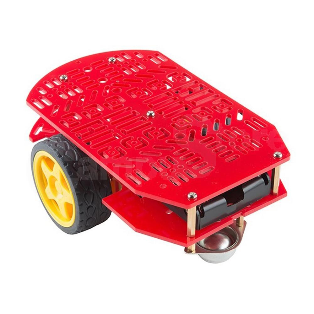
![]() Lo chassis va montato seguendo le dettagliate istruzioni fornite. Poiché per alimentare l’elettronica di bordo utilizzeremo un power bank, di quelli comunemente utilizzati per la ricarica dei cellulari, non sara’ necessario montare il supporto batterie compreso di solito nel package dello chassis.
Lo chassis va montato seguendo le dettagliate istruzioni fornite. Poiché per alimentare l’elettronica di bordo utilizzeremo un power bank, di quelli comunemente utilizzati per la ricarica dei cellulari, non sara’ necessario montare il supporto batterie compreso di solito nel package dello chassis.
![]() The chassis must be assembled following the detailed instructions provided. Since we will use a power bank to power the on-board electronics, commonly used for charging mobile phones, it will not be necessary to mount the battery holder usually included in the chassis package.
The chassis must be assembled following the detailed instructions provided. Since we will use a power bank to power the on-board electronics, commonly used for charging mobile phones, it will not be necessary to mount the battery holder usually included in the chassis package.
 Le schede di espansione –
  The expansion board
![]() Una volta completato il montaggio dello chassis, passiamo al montaggio dell’elettronica.
Una volta completato il montaggio dello chassis, passiamo al montaggio dell’elettronica.
La prima scheda da montare è la scheda a microcontrollore NucleoF401RE. Questa va montata nella parte posteriore dello chassis con la porta USB rivolta verso uno dei due lati, il sinistro oppure il destro. Le altre schede vanno impilate nella piedinatura standard preferibilmente nell’ordine, scheda sensori MEMS, scheda controllo motori, scheda ToF.
La scheda Tof monta un display con 4 cifre a 7 segmenti molto utile per il debug.
![]() Once the chassis is assembled, let’s move on to the electronics assembly.
Once the chassis is assembled, let’s move on to the electronics assembly.
The first board to be mounted is the NucleoF401RE microcontroller board. This must be mounted on the back of the chassis with the USB port facing either side, the left or the right. The other boards must be stacked in the standard pinout preferably in the order, MEMS sensor board, engine control board, ToF board.
The Tof board features a 4-digit 7-segment display that is very useful for debugging.

![]() La batteria power bank, va montata in maniera trasversale sull’asse delle due ruote motrici, con la porta USB preferibilmente dallo stesso lato della porta USB della scheda Nucleo.
La batteria power bank, va montata in maniera trasversale sull’asse delle due ruote motrici, con la porta USB preferibilmente dallo stesso lato della porta USB della scheda Nucleo.
Questa può essere fissata con due fascette.
![]() The power bank battery must be mounted transversely on the axis of the two drive wheels, with the USB port preferably on the same side of the USB port of the Nucleo board.
The power bank battery must be mounted transversely on the axis of the two drive wheels, with the USB port preferably on the same side of the USB port of the Nucleo board.
This can be fixed with two clamps.

![]() Sulla scheda Nucleo andiamo ad inserire la scheda dei sensori MEMS: la x-Nucleo IKS01A2
Sulla scheda Nucleo andiamo ad inserire la scheda dei sensori MEMS: la x-Nucleo IKS01A2
![]() On the Nucleo board we are going to insert the MEMS sensor board: the x-Nucleo IKS01A2
On the Nucleo board we are going to insert the MEMS sensor board: the x-Nucleo IKS01A2
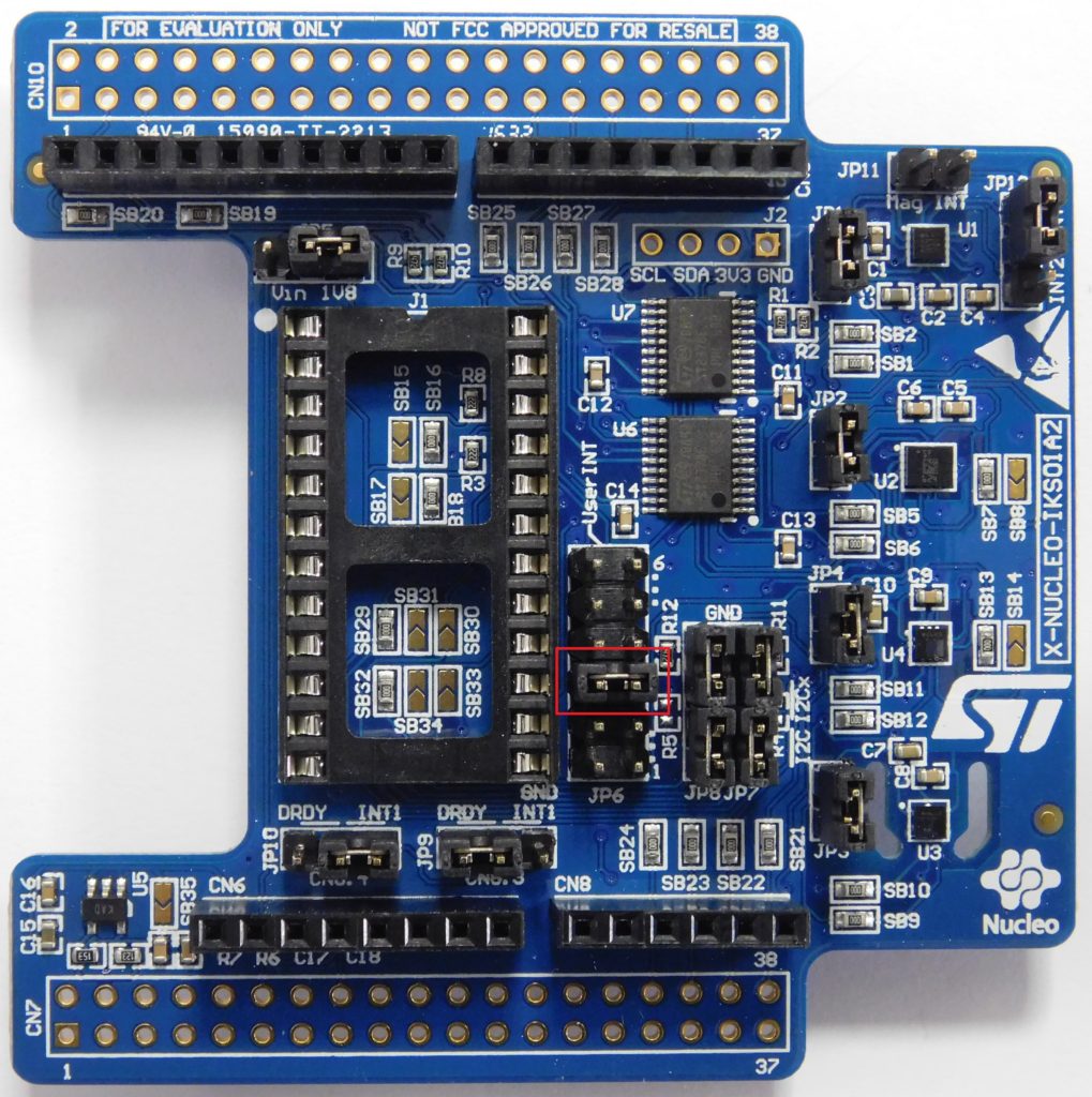
![]() Prima di montare su questa la scheda di controllo dei motori, assicurarsi di rimuovere il jumper evidenziato in rosso nella foto sopra.
Prima di montare su questa la scheda di controllo dei motori, assicurarsi di rimuovere il jumper evidenziato in rosso nella foto sopra.
Installiamo quindi la scheda di controllo dei motori, la x-Nucleo IHM12A1
Alla scheda motori vanno collegati i cavi provenienti dai due motori in corrente continua.
La scheda monta un connettore con il fissaggio a vite per 6 cavi. Due sono dedicati alla alimentazione esterna della scheda, mentre gli altri 4 sono per il collegamento dei due motori.
![]() Before mounting the motor control board on it, you have to be sure to remove the highlighted jumper in red in the picture above.
Before mounting the motor control board on it, you have to be sure to remove the highlighted jumper in red in the picture above.
We then install the engine control board, the x-Nucleo IHM12A1
The cables coming from the two DC motors must be connected to the motor board.
The board mounts a connector with screw fixing for 6 cables. Two are dedicated to the external power supply of the board, while the other 4 are for the connection of the two motors.

![]() Indichiamo il motore destro come motore A, ed il motore sinistro come motore B.
Indichiamo il motore destro come motore A, ed il motore sinistro come motore B.
Colleghiamo quindi il cavo di colore rosso proveniente dal motore destro , su A+ ed il cavo di colore nero proveniente dal motore destro su A-.
Facciamo la stessa cosa per il motore sinistro che va collegato al connettore B.
![]() We indicate the right engine as engine A, and the left engine as engine B.
We indicate the right engine as engine A, and the left engine as engine B.
Then connect the red cable coming from the right engine, on A + and the black cable coming from the right engine on A-.
We do the same thing for the left engine to be connected to the B connector.
| A+ | A- | B+ | B- |
|---|---|---|---|
| Right Engine red cable | Right Engine black cable | Left Engine red cable | Left Engine black cable |
La breadboard
![]() I morsetti GND e Vin della scheda motori vanno collegati alla breadboard sulla quale dovremo distribuire l’alimentazione.
I morsetti GND e Vin della scheda motori vanno collegati alla breadboard sulla quale dovremo distribuire l’alimentazione.
Montiamo quindi la breadboard sulla parte frontale dello chassis.
Ricordiamo che la beadboard ha due blocchi di righe ciascuna costituita da 5 colonne. Tali righe sono cortocircuitate.
![]() The GND and Vin terminals of the motor board must be connected to the breadboard on which we will have to distribute the power supply.
The GND and Vin terminals of the motor board must be connected to the breadboard on which we will have to distribute the power supply.
Then mount the breadboard on the front of the chassis.
Recall that the beadboard has two blocks of rows each consisting of 5 columns. These lines are short-circuited.

![]() Quindi per distribuire l’alimentazione, alla scheda motori, ai tre sensori IR ed al sensore di colore, preleviamo l’alimentazione dai pin 5 e 6, rispettivamente 5V e GND, e portiamoli alla breadboard su righe diverse utilizzando due cavi Dupont-MM.
Quindi per distribuire l’alimentazione, alla scheda motori, ai tre sensori IR ed al sensore di colore, preleviamo l’alimentazione dai pin 5 e 6, rispettivamente 5V e GND, e portiamoli alla breadboard su righe diverse utilizzando due cavi Dupont-MM.
![]() So to distribute the power supply, to the motor board, to the three IR sensors and to the color sensor, we take the power supply from pins 5 and 6, respectively 5V and GND, and bring them to the breadboard on different lines using two Dupont-MM cables.
So to distribute the power supply, to the motor board, to the three IR sensors and to the color sensor, we take the power supply from pins 5 and 6, respectively 5V and GND, and bring them to the breadboard on different lines using two Dupont-MM cables.

I sensori IR – The infrared sensorr
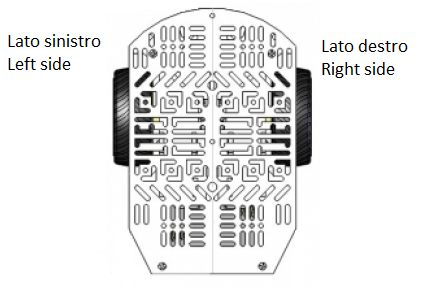
![]() Resta da montare i sensori IR ed il sensore di colore. Questi vanno montati nella parte frontale dello chassis, tutti dovranno guardare verso terra e saranno ad una distanza di circa mezzo centimetro da terra.
Resta da montare i sensori IR ed il sensore di colore. Questi vanno montati nella parte frontale dello chassis, tutti dovranno guardare verso terra e saranno ad una distanza di circa mezzo centimetro da terra.
L’obiettivo è disporre i sensori come riportato nella seguente figura.
![]() The IR sensors and the color sensor remain to be mounted. These must be mounted on the front of the chassis, all must look to the ground and will be at a distance of about half a centimeter from the ground.
The IR sensors and the color sensor remain to be mounted. These must be mounted on the front of the chassis, all must look to the ground and will be at a distance of about half a centimeter from the ground.
The goal is to place the sensors as shown in the following figure.
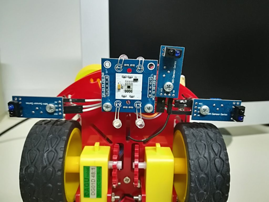
Il fissaggio dei sensori può essere realizzato utilizzando bulloni e dadi come proposto nella seguente fotografia.
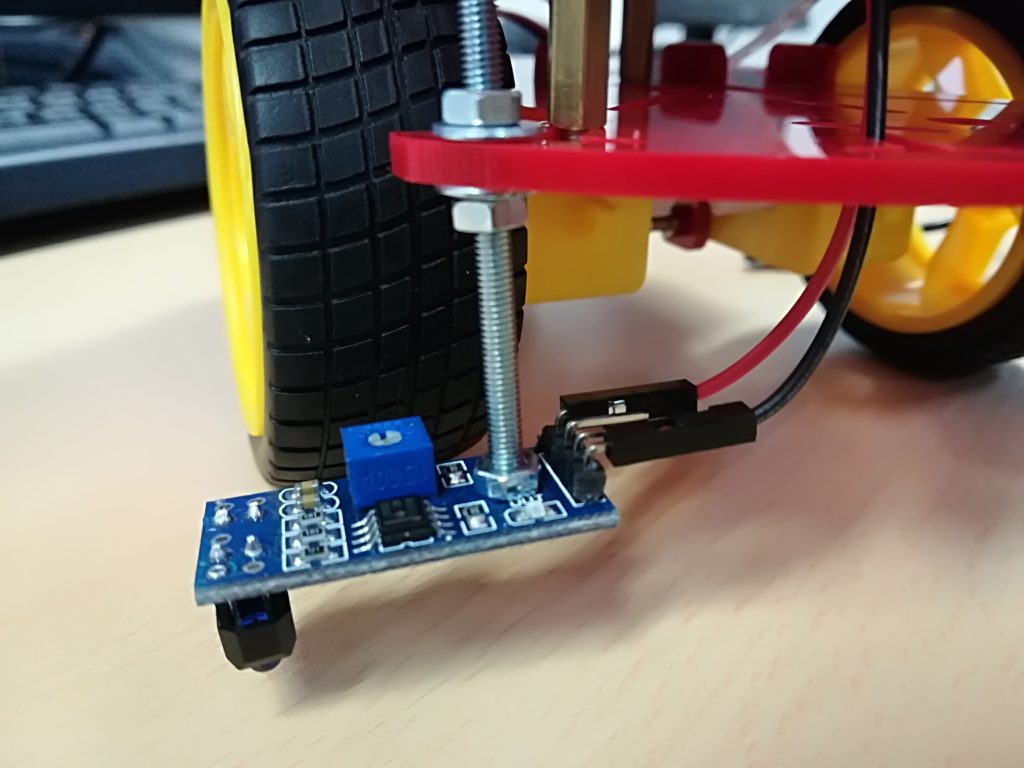
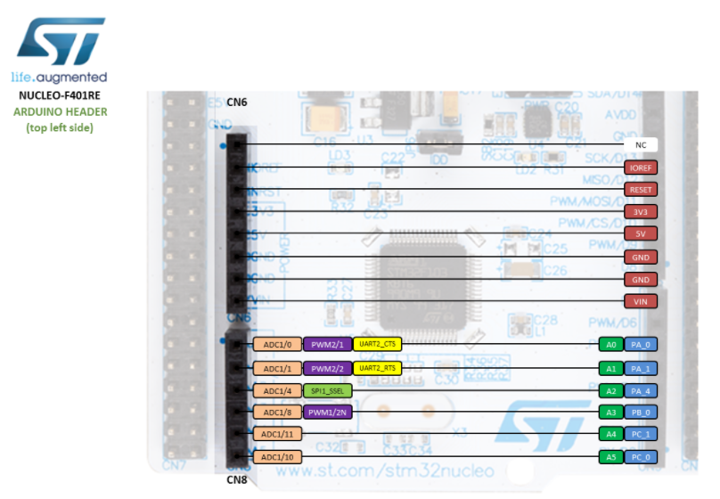
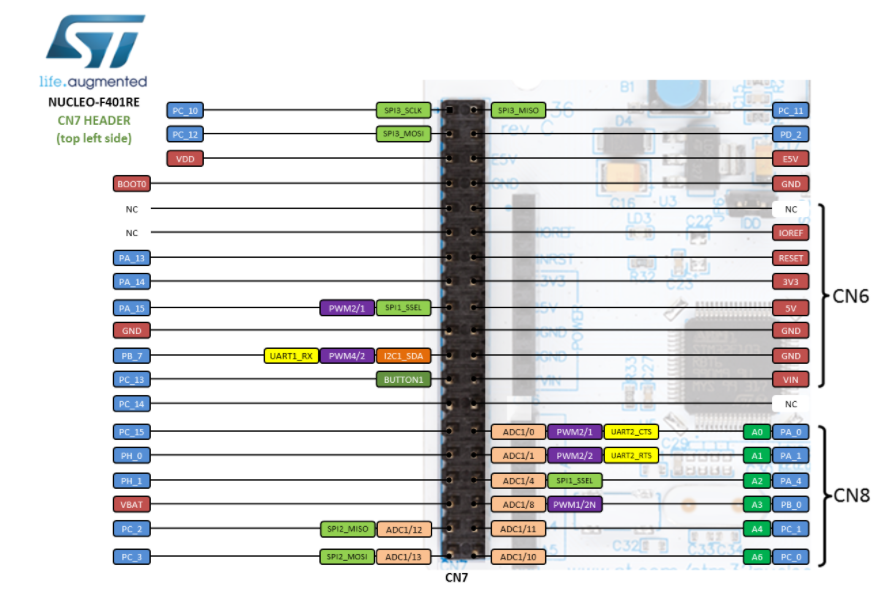
![]() Per tutti i sensori IR, oltre all’alimentazione che potremo prelevare dalla breadborad utilizzando due cavi dupont-MF per ciascun sensore, colleghiamo l’uscita analogica, che solitamente è indicata con la serigrafia A0 ai pin della scheda a microcontrollore come riportato nelle seguenti tabelle.
Per tutti i sensori IR, oltre all’alimentazione che potremo prelevare dalla breadborad utilizzando due cavi dupont-MF per ciascun sensore, colleghiamo l’uscita analogica, che solitamente è indicata con la serigrafia A0 ai pin della scheda a microcontrollore come riportato nelle seguenti tabelle.
Questi pin possono essere prelevati dall’ultima scheda montata, ossia quella dei sensori di prossimità ToF.
![]() For all the IR sensors, in addition to the power supply that we can take from the breadborad using two dupont-MF cables for each sensor, we connect the analogue output, which is usually indicated with the A0 silkscreen to the microcontroller board pins as shown in the following tables.
For all the IR sensors, in addition to the power supply that we can take from the breadborad using two dupont-MF cables for each sensor, we connect the analogue output, which is usually indicated with the A0 silkscreen to the microcontroller board pins as shown in the following tables.
These pins can be taken from the last mounted card, ie the ToF proximity sensors.
| Sensore IR (pin A0) | Pin NucleoF401RE |
|---|---|
| Destro - Right | A5 |
| Sinistro - Left | A4 |
| Centrale - Central | A1 |
Il sensore di colore – The color sensor
![]() Resta da collegare il sensore di colore. Notate che il sensore di colore, presenta i pin di alimentazione, Vcc e GND, su entrambe i lati, ma è sufficiente il collegamento di uno solo delle coppie di pin Vcc e GND. Anche in questo caso l’alimentazione va prelevata dalla breadboard utilizzando dei cavi dupont-MF. Qualora i pin sulla scheda breadboard non fossero sufficiente, con dei cavi dupont-MM si possono realizzare dei ponticelli verso una nuova riga, sia per i 5V che per il GND.
Resta da collegare il sensore di colore. Notate che il sensore di colore, presenta i pin di alimentazione, Vcc e GND, su entrambe i lati, ma è sufficiente il collegamento di uno solo delle coppie di pin Vcc e GND. Anche in questo caso l’alimentazione va prelevata dalla breadboard utilizzando dei cavi dupont-MF. Qualora i pin sulla scheda breadboard non fossero sufficiente, con dei cavi dupont-MM si possono realizzare dei ponticelli verso una nuova riga, sia per i 5V che per il GND.
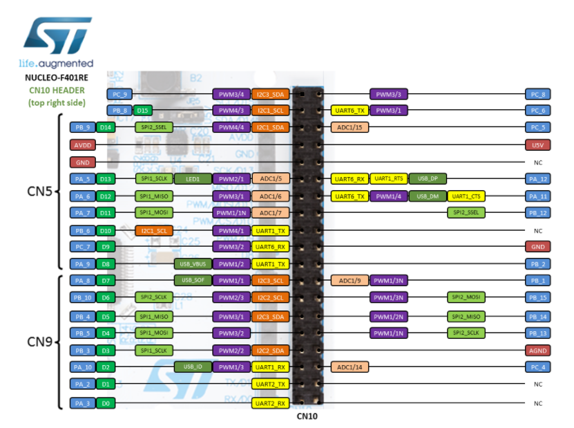
I pin S0, S1, S2, S3 ed OUT del sensore di colore, vanno collegati secondo la tabella seguente:
![]() The color sensor remains to be connected. Note that the color sensor has power pins, Vcc and GND, on both sides, but connecting only one of the Vcc and GND pin pairs is sufficient. Also in this case the power supply must be taken from the breadboard using dupont-MF cables. If the pins on the breadboard board are not sufficient, with dupont-MM cables you can make jumpers to a new line, both for 5V and for GND.
The color sensor remains to be connected. Note that the color sensor has power pins, Vcc and GND, on both sides, but connecting only one of the Vcc and GND pin pairs is sufficient. Also in this case the power supply must be taken from the breadboard using dupont-MF cables. If the pins on the breadboard board are not sufficient, with dupont-MM cables you can make jumpers to a new line, both for 5V and for GND.
The S0, S1, S2, S3 and OUT pins of the color sensor must be connected according to the following table:
| Sensore di colore - Color sensor | NucleoF401RE |
|---|---|
| S0 | PB_14 |
| S1 | PB_13 |
| S2 | PB_1 |
| S3 | PB_15 |
| OUT | PB_2 |
![]() Infine possiamo spegnere i LED montati sul sensore di colore, collegando a GND il pin LED.
Infine possiamo spegnere i LED montati sul sensore di colore, collegando a GND il pin LED.
E’ preferibile spegnere i LED, perché i colori che il sensore dovrà leggere sono realizzati con led RGB dei semafori e quindi che non necessitano di illuminazione.
![]() Finally we can turn off the LEDs mounted on the color sensor, connecting the LED pin to GND.
Finally we can turn off the LEDs mounted on the color sensor, connecting the LED pin to GND.
It is preferable to switch off the LEDs, because the colors that the sensor must read are made with RGB LEDs of the traffic lights and therefore do not require lighting.